| Centre Acoustique |
Laboratoire de Mécanique des Fluides et d'Acoustique UMR 5509 
|


Experimental Facilities and Equipment
The experimental facilities used by the Acoustics group are located in the
KCA, J12, I11, E6 and G8 buildings
on the ECL campus. The links below outline the main facilities.
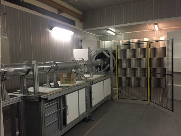
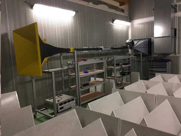
Subsonic and supersonic anechoic wind tunnel (KCA)
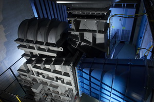
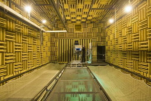
The two independent streams exhaust into the large anechoic room (10 x 8 x 8 m3) of the Center for Acoustics, on the right picture.
A subsonic stream powered by a double stage centrifugal fan (Howden, 800 kW, 9 tons, on the left picture) makes it possible to reach
a Mach number M = 0.5 with a mass flow rate of 19.4 kg/s in a 30 cm × 40 cm cross-section - for investigating airfoil noise for instance -
and M = 0.8 with a mass flow rate of 10.4 kg/s in a secondary nozzle diameter D = 20 cm, for the simulation of flight
effect on jet noise for instance.
The supersonic stream is generated by compressed dry air (dryer 10 kW) supplied by a centrifugal compressor (Centac C60MX2-SH Ingersoll-Rand, 350 kW; air cooler 10 kW), which allows continuous operation at a maximum mass flow rate up to 0.85 kg/s. Three electrical resistances, with a 64 kW maximal power, allow to heat the flow. The fully expanded Mach number Mj ranges up to 1.59 (NPR of about 4.17).
With funding support from
|
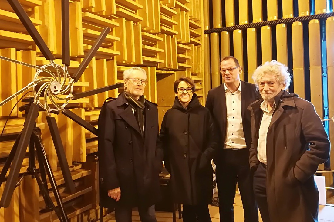
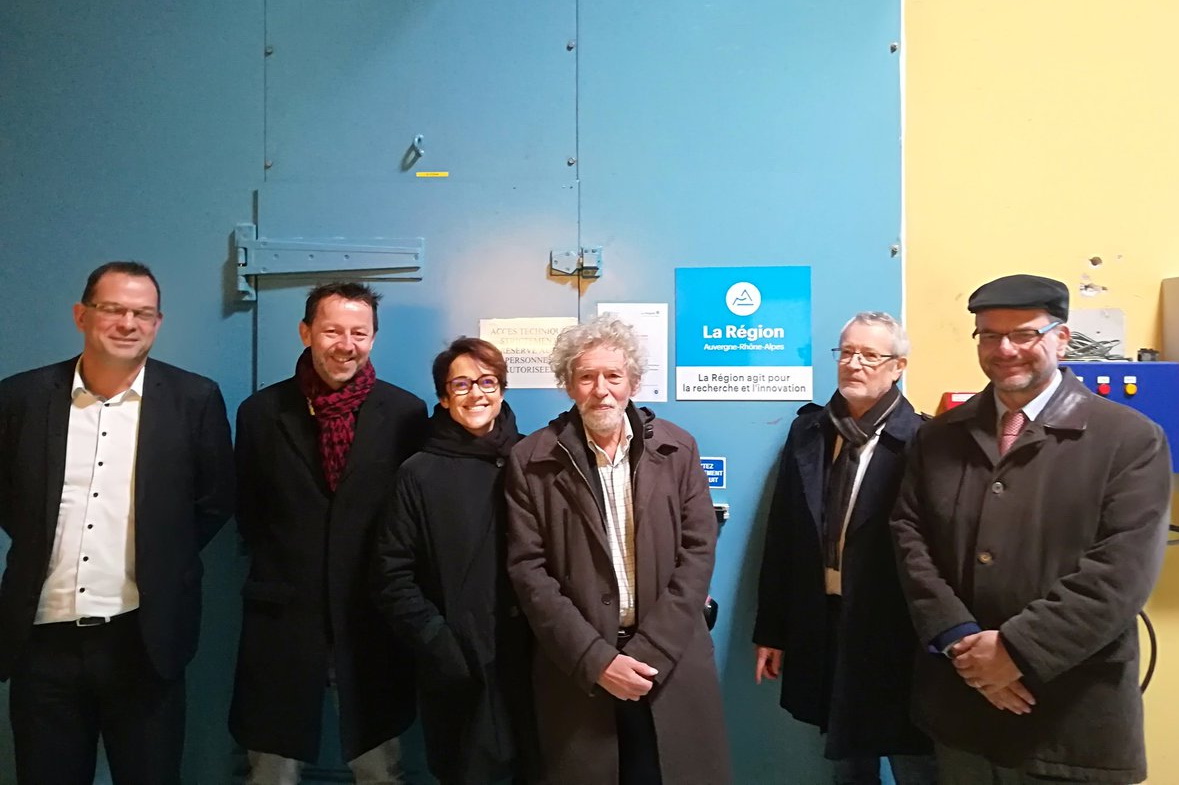
| Visite de Mme Annabel André Laurent (Vice-Présidente déléguée aux Entreprises, à l’emploi, au développement économique, au commerce, à l’artisanat et aux professions libérales de la région Auvergne-Rhône-Alpes) le 11 déc. 2018, accompagnée à gauche de Daniel Juvé (Prof. ECL), Christophe Ulrich (AVNIR Engineering) et Jean-Pierre Bertoglio (directeur de la recherche, ECL); et de Frédéric Antras (Aerospace Cluster AuRA) et Yves Desvallées (Safran Aircraft Engines) à droite. |
LP3 rig - ducted low-speed axial fan (J12)
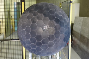
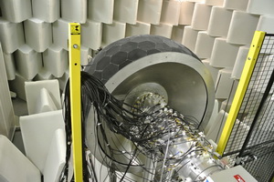
The LP3 test bench consists of a low speed aircraft HVAC fan (Technofan technology) with a heterogeneous stator
(3 vanes thickened due to structural purposes), a turbulence control screen (TCS, on the left picture),
an anechoic setting chamber to avoid end reflections
and 2 microphone arrays (upstream and downstream of the fan, on the right picture).
LP3 facility is used for fan noise studies, performed at a good scale to develop research work, e.g. advanced in-duct modal detection using a large number of pressure probes (128 microphones).
Caiman (J12)
Caiman wind tunnel: susbonic wind tunnel for the characterization of wall acoustic treatment.
Small subsonic anechoic wind tunnel (E6)
The subsonic flow is powered by three pairs of counter-rotating helicoid fans (40 kW) leading to a bulk velocity of 60 m/s
in an exhaust section of 30cm x 10cm.
The dimensions of the anechoic room are 6.10m (length) x 4.60m (width) x 3.80m (height).
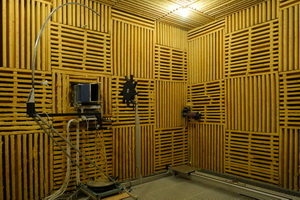
Coupled reverberation rooms (E6)
Phare-2 facility (G8)

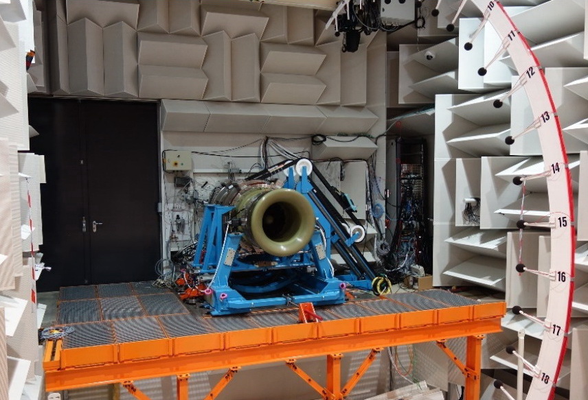
Characterization of fan noise in Phare-2 facility ( 1/3 scale of a real engine)
haut / top