(S. Prigent, E. Salze, E. Jondeau, P. Souchotte & C. Bailly)
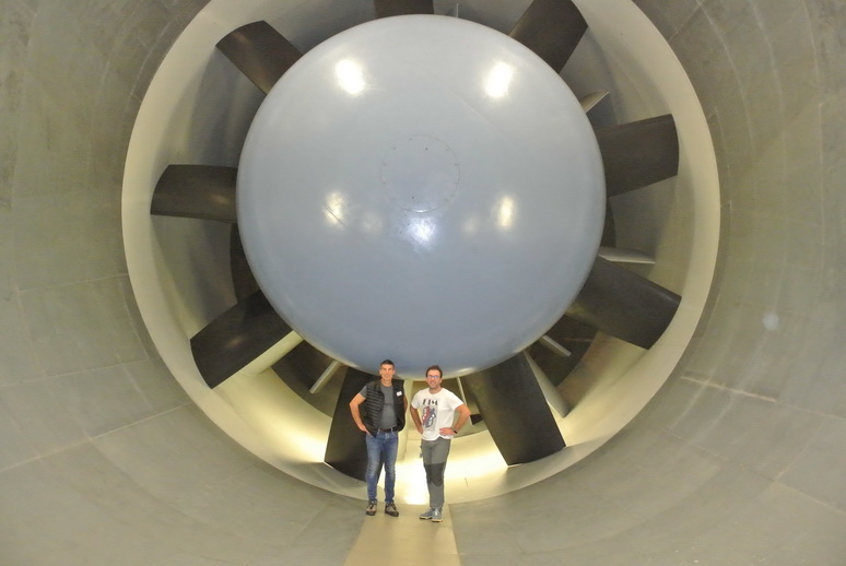
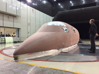
Canoble project of the EU’s CleanSky2 programme
Scale-one mock-up of the fore part of a Dassault Aviation business jet, in the S2A wind tunnel.
Hot-wires and hot-films have been used to characterise the boundary layer while newly developed antennas of digital MEMS microphones
served for the measurement of wall pressure.
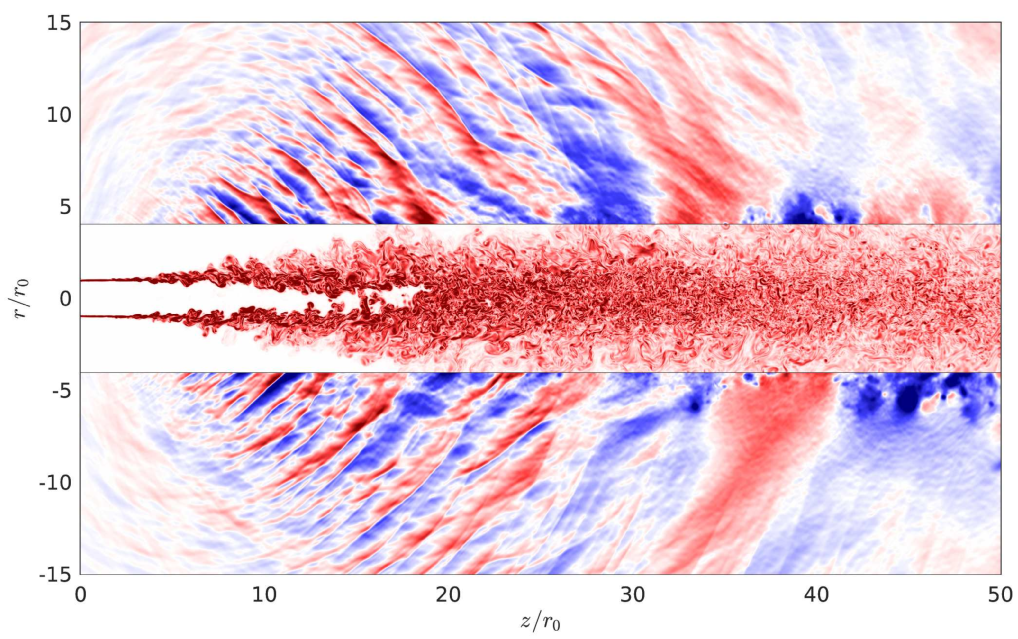
Numerical simulation of an isothermal supersonic jet at Mach 2,
snapshot of the vorticity field in the flow, and of the fluctuating pressure field outside.
The value of the Reynolds number is 50 000 (based on the jet diameter 2 r0 and exit velocity uj).
The pressure fluctuations range from -3000 to 3000 Pa, and the vorticity norm from 0 to 3uj/r0
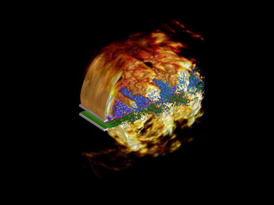
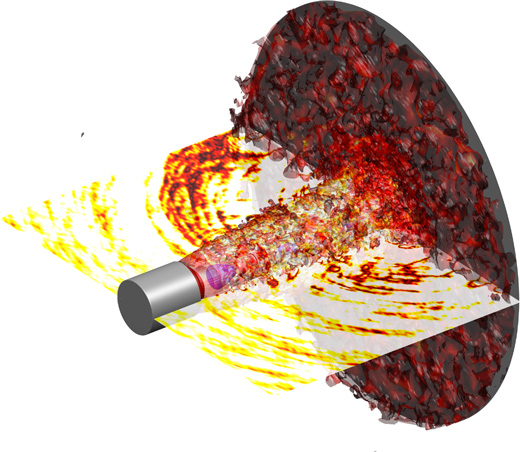
Visualisation tridimensionnelle d'un jet rond supersonique sous-détendu impactant une paroi solide avec un angle de 90 degrés.
Le développement de la turbulence dans le jet et sur la paroi après l'impact y est bien visible. Des ondes acoustiques générées
au niveau de la région d'impact apparaissent également clairement dans le champ de pression représenté dans un plan transverse.
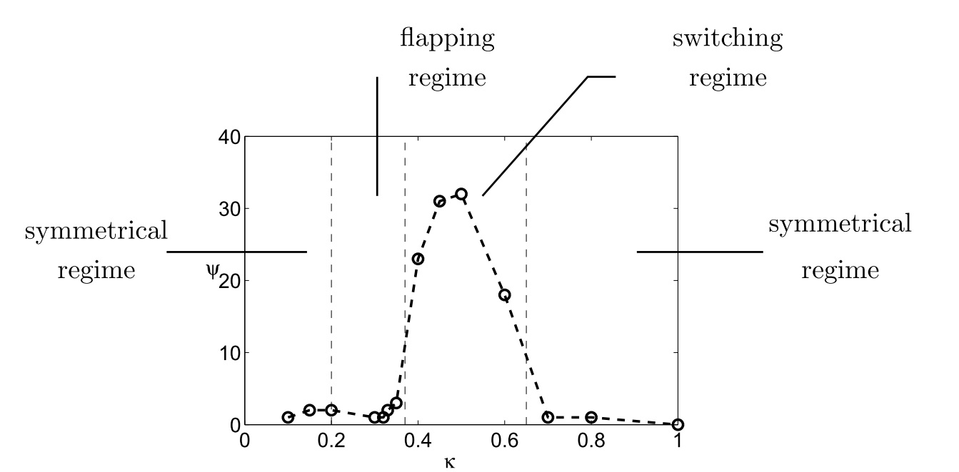
Mean flow rotation phi in degrees around the vertical axis as a function of kappa = height/depth.
Dashed vertical lines denote separations between different regimes, and symbols, to reported computations.
Switching regime kappa=0.32.
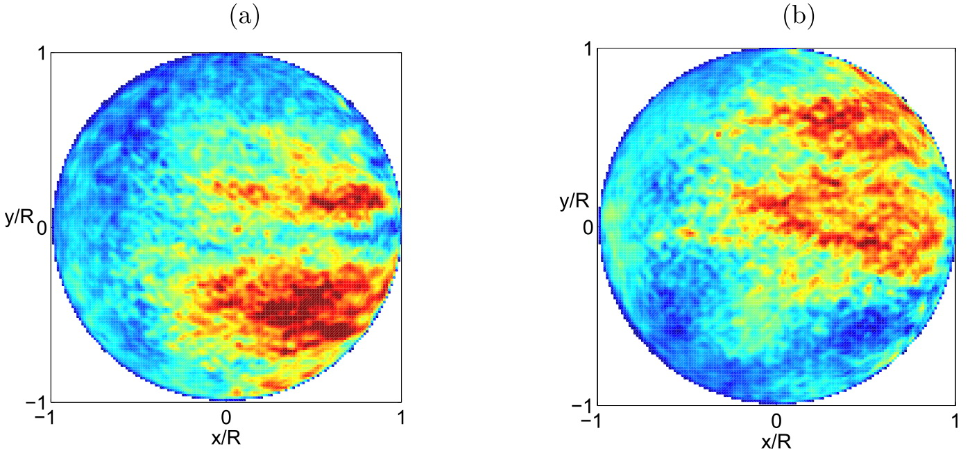
Instantaneous velocity normalized by the free stream flow velocity, in the z/H = - 0.1 plane,
at times (a) t x Uinfty/D = 300 and (b) at t x Uinfty/D = 900.
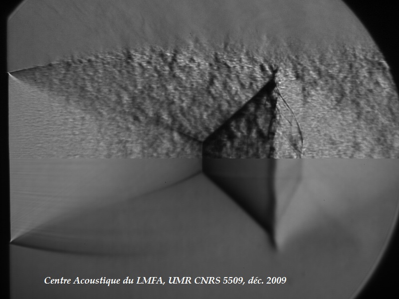
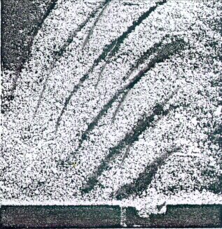
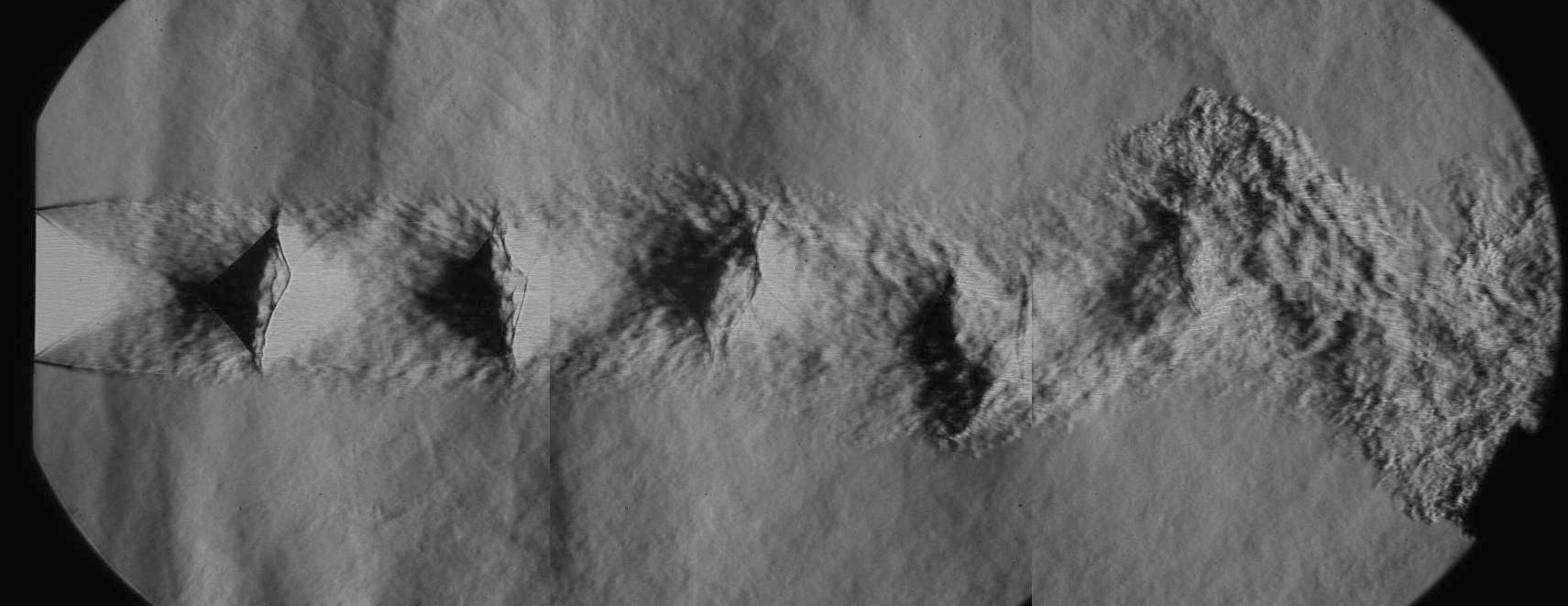
Schlieren picture of an underexpanded jet plume (convergent nozzle, Mj=1.50, Mflight=0.39, exposure time 6.7 µs).
The first shock is seen to be twisted within the jet plume, denoting a strong oscillation amplitude,
and a large flapping motion of the jet occurs further downstream.
Ph.D. Thesis of Benoît André, in collaboration with Snecma and Airbus-France.
Large eddy simulation of an overexpanded supersonic jet
Snapshot of density gradient norm in gray scale, azimuthal vorticity in
color scale in the jet, and fluctuating pressure in color scale outside the jet.
Pressure levels from -8000 to 8000 Pa (color bar from -5000 to 5000 Pa).
Reynolds number of 10^5, exit Mach number of 3.30,
static pressure and temperature of 0.5x10^5~Pa and of 360~K.
Ph.D. Thesis of Nicolas de Cacqueray, in collaboration with the CNES
Superposition of density gradient (gray scale), and of pressure (color scale).
Shock Mach number of 1.2 and maximum vortex Mach number of 0.25.Bogey, de Cacqueray & Bailly (2009, JCP)
Aeroacoustics phenomena in subsonic and transonic ducted flows
Strong interactions between shock oscillations, internal aerodynamic noise and acoustic duct modes
are often observed in confined flows but are undesirable to prevent vibrations and fatigue of structures.
In order to compute this kind of phenomena, a numerical solver called
SAFARI (Simulation of Aeroacoustics in Fluids And Resonances and Interactions, EDF) has been developed.
Compressible Navier-Stokes equations are solved using high-order finite difference schemes.
A non-linear adaptive filter is implemented to capture strong shock waves and a high-order overset
grid ability is introduced in order to treat complex geometries. These numerical techniques allow
to carry out direct simulation of aeroacoustic couplings in subsonic and transonic flows.
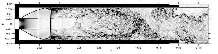
A transonic flow passing a sudden expansion in a duct is studied. For certain values of the
pressure ratios tau (tau = Poutlet/Pinlet), the supersonic
expansion ends up after a normal shock. Strong coupling between the self-sustained oscillations
of the normal shock and the longitudinal acoustic modes is captured as in the experiments.
An instantaneous snapshot of the density gradient modulus is represented in a plane
perpendicular to the spanwise direction. Others flow regimes have been studied. For lower
pressure ratios, the flow is entirely supersonic with oblique shocks. For higher pressure ratios,
the flow is asymmetric and exhibits shock cells.
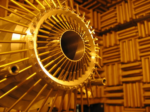
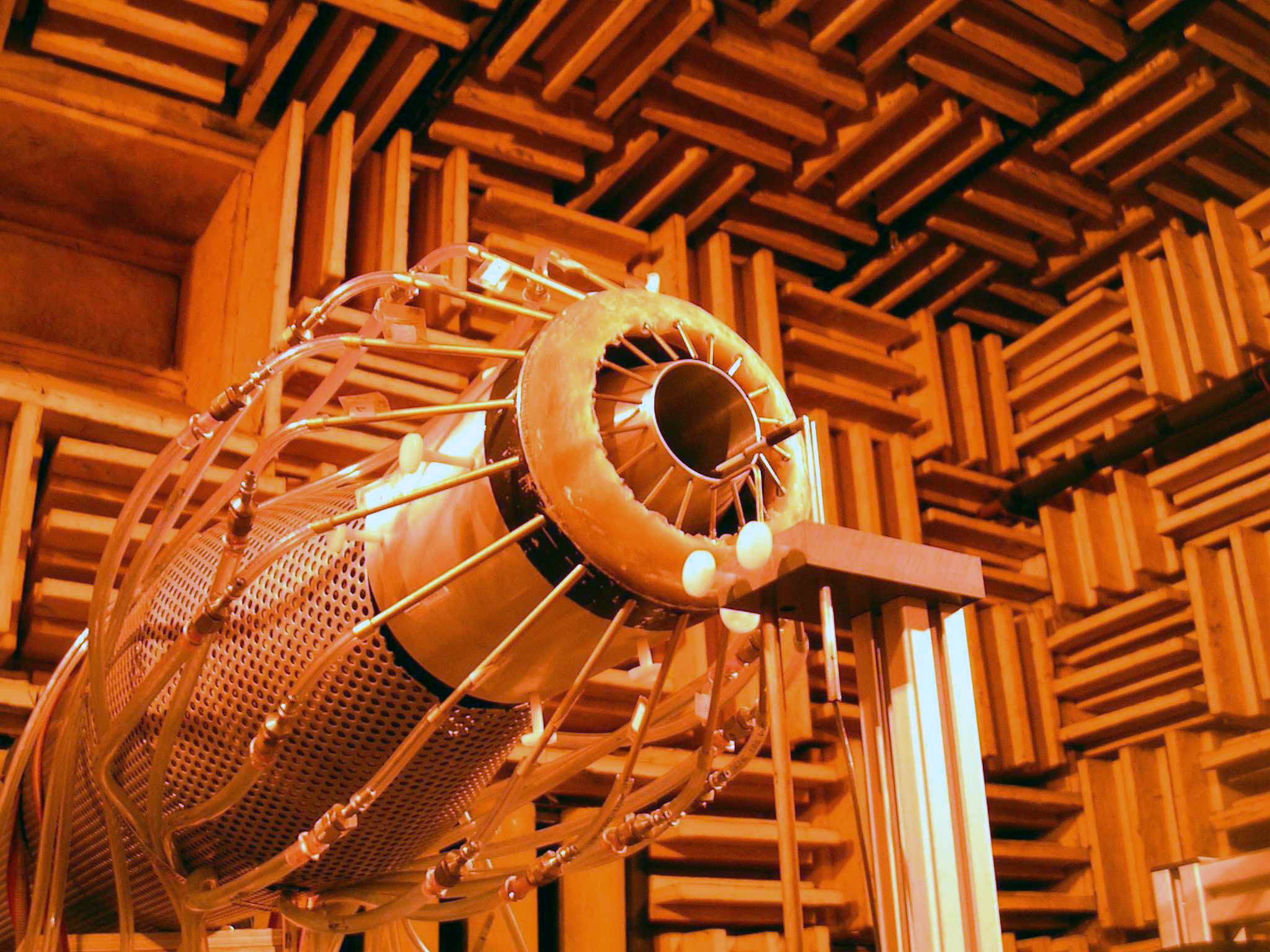
The effects of a fluidic control on the aeroacoustic characteristics of a Mach 0.9 high-Reynolds axisymmetric
jet are investigated experimentally. The air-microjet system comprised up to 36 impacting microjets
directed towards the jet centerline, and was designed to allow the modification of various
geometrical and aeraulical microjet parameters. A significant noise reduction was obtained for the entire
range of theta, the angle theta designating the direction of noise emission. The dependency
of the noise reduction with respect to parameters of the microjets system was studied and three parameters
were mainly considered: the outgoing mass flux per microjet, the number of microjets and their layout
in the azimuth of the main jet. Depending on the microinjection flow parameters, the global jet-noise
reduction varied from 0 to 1.8 dB, showing some non-monotonic behaviors due to the change between
subsonic and supersonic regimes of the microjets. For low values of number of microjets, the microjets
seem to act independently, which was confirmed by aerodynamic studies by Stereoscopic Particle Image
Velocimetry. These studies indicated a strong correlation between the maximum level of
turbulence just behind the nozzle exit and the high-frequency noise, previously shown to potentially
balance the acoustic benefits obtained for lower frequencies. The maximum level of turbulence measured
at the longitudinal position corresponding to half the potential core length was shown to be also
highly correlated to the jet noise reduction.
Generation of screech tones in an underexpanded supersonic jet
Snapshot of the density modulus, of the spanwise vorticity and of the near-field pressure,
in a plane perpendicular to the spanwise direction. The nozzle lips are represented in black.
(fully expanded jet Mach number 1.55, Reynolds number 60,000)
Compression shocks corresponding to high-density gradients are observed inside the jet plume.
Upstream-propagating wave-fronts associated with screech tones radiation are also clearly visible
on either side of the jet. A further study of the simulation data have permitted to provide evidences
of the connection between the shock-leakage process (Suzuki & Lele, JFM, 2003)
and the generation of screech tones.
The jet operates at off-design conditions with a Mach number M = 1.55.
The Reynolds number is Re = 100000. A snapshot of instantaneous spanwise vorticity is shown
in purple and green, and corresponding isosurfaces of pressure are in yellow.
Upstream-propagating wavefronts, corresponding to screech tones, are visible on both sides of the jet.
DFG - CNRS project with T.U. Munich - Pr. Friedrich.
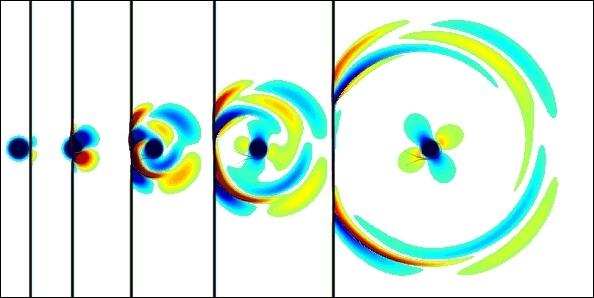
Influence of the Reynolds number on the turbulent development of transitional,
isothermal subsonic round jets and on their radiated noise. The Mach number of the jets is 0.9,
and their Reynolds numbers are: (a) 1,700; (b) 2,500; (c) 5,000 and (d) 400,000.
The flow and the acoustic fields are calculated directly using compressible Large Eddy Simulations.
The vorticity norm is represented in the jet flow, and the fluctuating pressure is visualized outside.
Calcul direct du bruit d'un jet subsonique circulaire par simulation compressible
des grandes échelles. Représentation d'une composante de la vorticité dans l'écoulement,
et du champ acoustique à l'extérieur.
Nombre de Mach M = 0.9
Nombre de Reynolds ReD = 6.5 x 10⁴
Calcul direct du bruit d'une couche de mélange par simulation compressible des
grandes échelles. Représentation d'une composante de la vorticité dans l'écoulement,
et du champ acoustique à l'extérieur.
Calcul direct du bruit d'un écoulement affleurant une cavité.
Représentation du gradient transversal de la masse volumique obtenu
par DNS à gauche, et expérience de Karamcheti (NACA 3847, 1955) à droite.
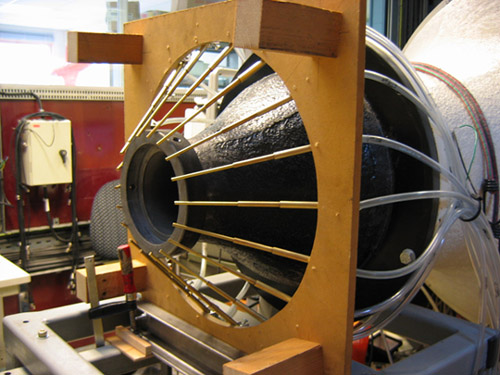
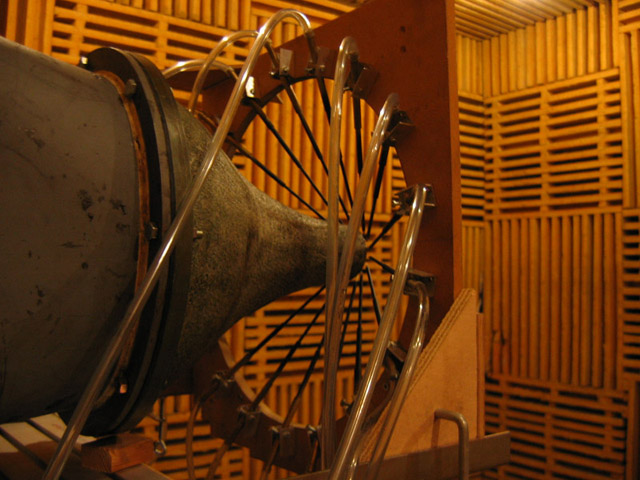
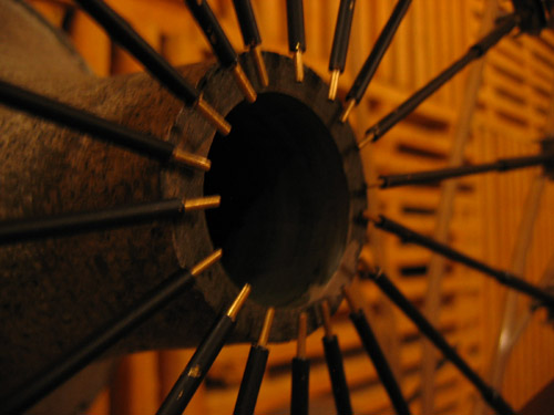
Contrôle de jet avec pour objectif la réduction du bruit de jet.
A ce titre, une des voies explorées est le contrôle du développement de la couche de mélange du jet et la taille
des structures principales qui y sont générées, sources majeures de bruit. Le système de contrôle utilisé dans la cadre de
cette étude est constitué de 18 injecteurs régulièrement espacé dans la direction azimuthale,
tel que le représente la figure suivante:
Système d'injection d'air à 18 injecteurs secondaires
paramétrable géométriquement
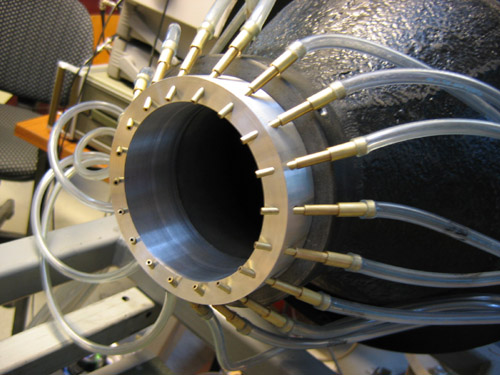
Système d'injection d'air à 18 injecteurs secondaires à
géométrie fixée (angle d'injection 45°)
Nos études concernent d'une part les grandeurs aérodynamiques de l'écoulement,
déterminées par anémométrie à fil chaud et des visualisations par Vélocimétrie à Images de Particules (PIV).
Le jet testé est caractérisé par un nombre de Mach M=0.12 et un nombre de Reynolds Re=3.10^5.
Notre objectif est de déterminer les mécanismes d'interaction entre les jets secondaires
et la couche de mélange du jet principal et les effets de ces mécanismes sur les grandeurs
caractéristiques de la turbulence dans la couche de mélange. Un optimum au sens de la réduction du maximum
de ces grandeurs turbulentes a pu être isolé en fonction du débit dans les injecteurs secondaires,
et des différents paramètres géométriques d'injection (angle d'injection, distance entre le point d'impact
des jets secondaires sur la couche de mélange et la buse du jet principal, distance entre l'origine
des jets secondaires et le point d'impact des jets secondaires sur la couche de mélange, etc ...)
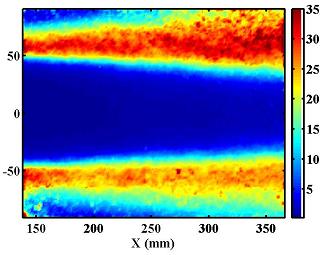
Vorticité dans la couche de mélange entre 0D et 0.5D;
jet seul (gauche) et jet contrôlé (droite)
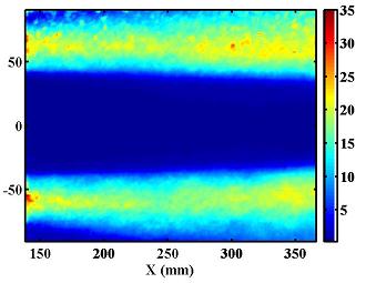
Intensité turbulente longitudinale dans le jet entre 1.5D et 3D;
jet seul (gauche) et jet contrôlé (droite)
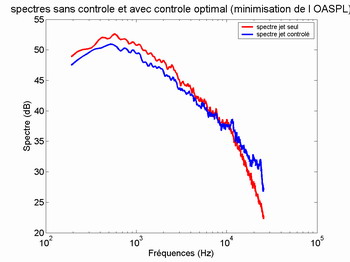
D'autre part des essais acoustiques sont menés en chambre anéchoïque,
à M=0.28 et Re=3,2.105, afin de comparer l'efficacité en terme
de réduction de bruit des différentes configurations testées durant l'étude aérodynamique,
par des mesures de pression acoustique en champ proche et en champ lointain.
Spectre de bruit en champ lointain :
jet seul (rouge) et jet contrôlé (bleu)


 (S. Prigent, E. Salze, E. Jondeau, P. Souchotte & C. Bailly)
 download pdf
 André et al., 2011, Phys. Fluids
 Click on the picture to enlarge !